
Core Fundamentals of Marine Electrical Systems
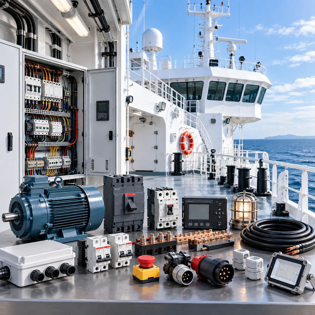
Designing and maintaining a reliable boat network starts with understanding the core components of marine electrical systems. On the water, power is life support. A properly engineered setup must withstand moisture, constant vibration, and corrosive salt air while seamlessly managing two fundamentally distinct electrical circuits: DC battery power and AC grid power.
[ Shore Power 120V/240V AC ] [ Marine Genset ]
│ │
└───────────┬────────────────┘
▼
[ AC Distribution Panel ]
│
┌───────────────┴───────────────┐
▼ ▼
[ AC Appliances ] [ Marine Inverter/Charger ]
│
▼
[ Alternator / Solar ] ────► [ DC Battery Bank (12V/24V/48V) ]
│
▼
[ DC Distribution Panel ]
│
[ Navigation, Pumps, Lights ]
Direct Current (DC) vs. Alternating Current (AC) Onboard
Modern vessels operate as hybrid microgrids. We balance low-voltage DC for vital operations with high-voltage AC for domestic comforts:
-
- Direct Current (DC): The backbone of marine safety. DC flows continuously in one direction from your boat battery bank. It powers critical baseline hardware—bilge pumps, navigation lights, chartplotters, communications, and engine starters. Because DC runs directly off chemical storage, these systems stay alive even when completely disconnected from land.
- Alternating Current (AC): Standard household power that alternates direction periodically. AC runs heavy consumer loads like air conditioning, induction cooktops, water heaters, and refrigeration. It is supplied exclusively by shore power, an onboard genset, or pulled from DC banks via a marine inverter charger.
Standard Marine Voltages: 12V, 24V, and 48V DC Systems
Choosing the right operating voltage determines wire gauge sizing, weight distribution, and overall system efficiency:
| System Voltage | Primary Application | Key Advantage | Key Limitation |
|---|---|---|---|
| 12V DC | Runabouts, dayboats, small cruisers (<35 ft) | Universal parts availability; lowest component cost | Heavy copper cabling required for high loads |
| 24V DC | Mid-size yachts, trawlers (35–60 ft), heavy bow thrusters | Cuts current (amperage) in half; smaller wire sizes | Fewer off-the-shelf direct 12V electronics |
| 48V DC | Modern catamarans, electric propulsion, massive LiFePO4 banks | High efficiency; runs high-tonnage AC without a generator | Requires DC-DC converters for standard 12V electronics |
Shore Power Basics and AC Line Voltages (120V/240V)
When docking, a vessel links to terrestrial utility grids through a dedicated shore power inlet to recharge house banks and handle domestic loads:
-
- 120V / 30A Connections: The standard North American utility configuration for vessels under 40 feet, supplying up to 3.6 kW of continuous power.
- 120V/240V / 50A Connections: Split-phase service providing up to 12.0 kW, essential for multi-zone climate control, heavy battery chargers, and full electric galleys.
- Isolation and Safety: Connecting AC shore cords directly links your vessel to dockside earth grounds, demanding robust safety barriers to block stray ground currents and keep AC power clean.
Power Generation Components in Boats
Marine Alternators and High-Output Smart Regulators
Standard automotive alternators cannot handle the continuous, high-current demands of a boat. We rely on heavy-duty marine alternator units equipped with external multi-stage smart regulators.
-
- Smart Multi-Stage Charging: External regulators adjust voltage dynamically across bulk, absorption, and float stages.
- Thermal Protection: Temperature sensors throttle back output if the alternator or battery bank gets too hot, preventing burnt windings and damaged cells.
- Lithium Compatibility: Smart regulators dial in exact charge profiles required for high-acceptance LiFePO4 chemistry.
Marine Diesel and Gas Gensets
When high-draw AC loads like air conditioning, watermakers, and heavy induction cooktops run away from dockside power, an onboard marine generator (genset) takes over. Marine gensets feature ignition-protected components, sound shields, and dedicated heat exchangers to supply stable 120V/240V AC power while underway or at anchor. Using verified marine electrical components, parts, and spare parts for routine genset servicing prevents costly mid-voyage power failures.
Solar Panels and MPPT Charge Controllers
Renewable marine power delivers silent, continuous charging to counter passive daily loads like refrigeration, sensors, and safety gear.
-
- Marine-Grade Solar Arrays: Monocrystalline rigid panels mounted on arches or semi-flexible panels fitted to canvas dodgers survive salt spray and wind load.
- MPPT Charge Controllers: Maximum Power Point Tracking controllers convert excess solar voltage into usable charging current, boosting harvest efficiency by up to 30% compared to basic PWM regulators.
Shore Power Inlets and Shore Cords
Dockside charging relies on heavy-duty, weather-resistant connections designed to handle high amperage without arcing or voltage drops.
| Component | Standard Ratings | Key Function |
|---|---|---|
| Shore Power Inlet | 30 Amp 120V / 50 Amp 120/240V | Corrosion-resistant hull inlet that receives dockside AC power. |
| Marine Shore Cord | 10/3 AWG (30A) or 6/4 AWG (50A) | Heavy-gauge, UV-resistant, flexible cable with locking watertight collars. |
| Inlet Breakout Box | Matches inlet amperage | Houses direct strain relief and initial overcurrent protection right behind the hull. |
Marine Energy Storage: Battery Bank Components
Starting vs. Deep-Cycle House vs. Thruster Battery Banks
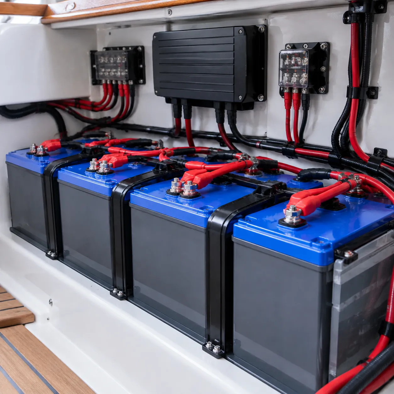
We never rely on a single battery to handle every onboard job. Splitting batteries into dedicated banks prevents you from getting stranded with a dead engine miles offshore:
-
- Starting Banks: Engineered to deliver massive bursts of cranking amps for short bursts (5 to 10 seconds) to start main engines and gensets. They feature thin, spongy lead plates that quickly recharge once the engine runs.
- Deep Cycle House Battery Banks: Built with dense, thick plates designed to deliver steady current over extended hours. This bank handles continuous loads like refrigeration, chartplotters, cabin lighting, and inverters, happily discharging down to 50% (or 80% for lithium) without premature failure.
- Dedicated Thruster/Windlass Banks: High-load equipment like bow thrusters and anchor winches draw huge current spikes. Locating a dedicated bank close to these forward loads avoids heavy voltage drop across long cable runs.
Marine Battery Types Compared
Selecting the right chemistry for a boat battery bank balances usable capacity, weight, service life, and upfront investment:
| Battery Chemistry | Usable Capacity (DoD) | Cycle Life (Est.) | Maintenance | Key Advantages |
|---|---|---|---|---|
| Flooded Lead-Acid (FLA) | ~50% | 300–500 cycles | High (fluid checks, venting) | Lowest initial cost; proven technology |
| AGM (Absorbed Glass Mat) | ~50% | 400–800 cycles | Zero (sealed) | Shock-resistant; no spills; faster charging |
| Gel Cell | ~50% | 500–1,000 cycles | Zero (sealed) | Deep discharge recovery; sensitive to overcharge |
| Lithium Iron Phosphate (LiFePO4) | 80%–100% | 3,000–5,000+ cycles | Zero (sealed) | Ultra-lightweight; flat voltage curve; rapid charging |
When retrofitting an older vessel, sourcing hardware from reliable sources for marine electrical supplies ensures your battery installation strictly complies with ABYC electrical standards for retention, ventilation, and terminal shielding.
Battery Management Systems (BMS) and Cell Balancers
Upgrading to lithium chemistries requires an intelligent battery management system (BMS). Unlike drop-in lead batteries, LiFePO4 cells must operate within tight voltage and temperature boundaries.
The BMS acts as the bank's digital bodyguard:
Under/Over-Voltage Protection: Instantly isolates the bank before individual cells drop below critical voltage or overcharge.
Cell Balancing: Equalizes charge levels across individual series cells to maximize pack capacity and overall lifespan.
Temperature Cutoffs: Disables charging currents when ambient temperatures drop below freezing (32°F/0°C) to prevent permanent lithium plating damage.
Alternator Protection: Communicates with external regulators to shut down charging safely, protecting your marine engine electrical parts and replacement components from damaging load dump spikes.
Power Conversion and Charging Components of Marine Electrical Systems
Power conversion gear bridges the gap between shore power, generation sources, and onboard loads. Managing energy conversion efficiently keeps your battery bank healthy and guarantees stable voltage for delicate electronics.
| Conversion Equipment | Primary Function Onboard |
|---|---|
| Smart Marine Charger | 3–4 stage charging tailored to specific battery chemistry |
| Pure Sine Wave Inverter | Clean 120V/240V AC power conversion from DC banks |
| Marine Inverter Charger | Combined conversion, charging, and auto-transfer switch |
| DC-to-DC Converter | Chemistry isolation (e.g., Lead to Lithium) & step-down |
Multi-Stage Smart Marine Battery Chargers
Standard automotive chargers overcharge and boil electrolyte out of marine cells. We rely strictly on multi-stage smart marine battery chargers that automatically transition through dedicated charge phases:
-
- Bulk Stage: Delivers maximum rated current up to roughly 80% capacity.
- Absorption Stage: Holds voltage constant while tapering current to finish the charge safely.
- Float Stage: Maintains fully charged voltage to counter self-discharge without overheating cells.
- Storage/Equalization Mode: Prevents sulfation on flooded banks or maintains balanced cell state for long layups.
Pure Sine Wave vs. Modified Sine Wave Inverters
Inverters convert stored DC battery power into usable AC household current.
-
- Pure Sine Wave Inverters: Replicate smooth utility grid power. They are essential for running sensitive marine electronics, refrigeration compressors, induction cooktops, medical devices, and laptops without humming, overheating, or circuit damage.
- Modified Sine Wave Inverters: Produce a stepped, blocky wave. While cheaper, they run motors hotter, create audio/visual interference on displays, and can destroy sensitive digital controls. For reliable offshore operation, pure sine wave is our absolute baseline standard.
Integrated Marine Inverter Charger Units
Combining a multi-stage charger, pure sine wave inverter, and an automatic transfer switch into a single chassis saves valuable space in the engine room or utility locker. An integrated marine inverter charger immediately transfers AC loads to battery power when shore power drops out, preventing navigation computers and onboard refrigeration from rebooting. When sourcing replacement conversion gear, choosing certified marine spare parts equipment ensures full compliance with marine safety standards.
DC-to-DC Converters and Voltage Stabilizers
Modern marine networks frequently blend multiple voltages and battery types:
-
- Alternator-to-Lithium Charging: DC-to-DC chargers limit current draw to prevent standard marine alternators from burning out when charging low-resistance LiFePO4 banks.
- Voltage Step-Down (24V/48V to 12V): Delivers clean 12V power for standard VHF radios, navigation lights, and MFDs from larger propulsion or house banks.
- Voltage Stabilization: Eliminates voltage drops during engine cranking to protect sensitive electronics from unexpected reboots.
Power Distribution and Circuit Protection: Key Components of Marine Electrical Systems
Main Battery Disconnect Switches and Automatic Charging Relays (ACR)
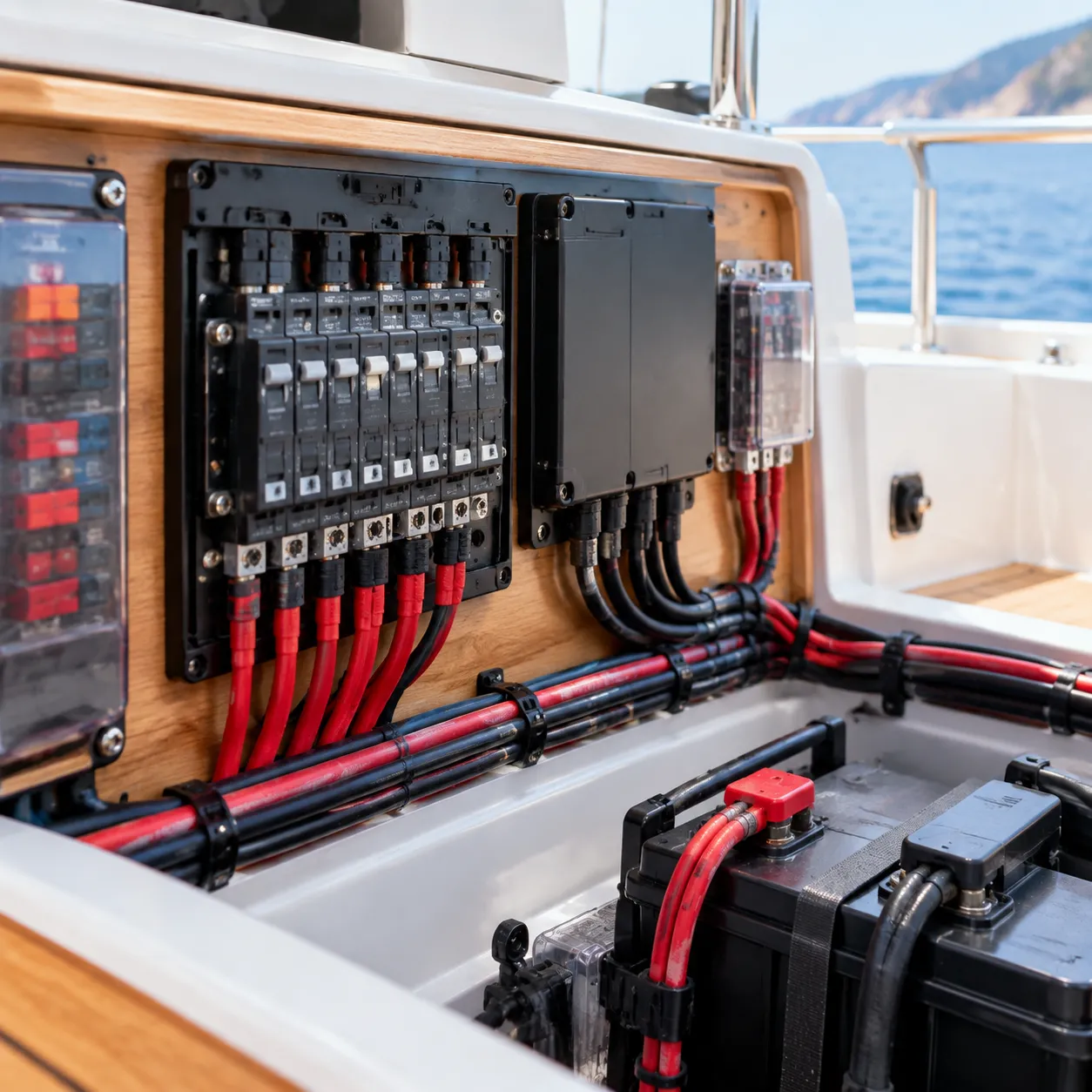
The main battery switch serves as the master shutoff for your DC network, allowing complete isolation during maintenance, storage, or an emergency.
-
- Manual Battery Switches: High-amperage, ignition-protected switches (Off/1/2/Both) handle massive cranking loads while isolating starter banks from house loads.
- Automatic Charging Relays (ACR): An ACR dynamically shares charging current across separate banks. When engines run or solar chargers produce power, the relay closes to charge both banks simultaneously. Once charging ceases, the ACR automatically isolates the starting battery to guarantee engine startup power.
[ Alternator / Charger ]
│
▼
[ House Battery Bank ]
│
┌─────────┴─────────┐
▼ ▼
[ Main Switch ] [ ACR / VSR ] ──► [ Starter Battery ]
│
▼
[ DC Distribution Panel ]
AC and DC Marine Distribution Panels and Circuit Breakers
A well-engineered AC DC distribution panel organizes your boat's branch circuits and provides fast reset capability when faults occur.
-
- DC Electrical Panels: Distribute low-voltage power (12V, 24V, or 48V) to navigation electronics, bilge pumps, refrigeration, and cabin lights using specialized marine circuit breakers.
- AC Distribution Switchboards: Manage alternating current from shore power or inverters, equipped with reverse polarity indicators, lockouts for transfer switches, and high-interrupt capacity breakers.
When designing or upgrading panels, sourcing certified marine electrical parts and equipment ensures full compliance with ABYC electrical standards and prevents premature switchgear failure.
Marine-Grade Fuses: Choosing the Right Overcurrent Protection
Fuses must be sized to protect the smallest conductor in the circuit and possess adequate Ampere Interrupting Capacity (AIC) to handle potential short-circuit spikes.
| Fuse Type | Common Rating | Primary Application | Key Advantage |
|---|---|---|---|
| Class T Marine Fuse | 110A – 400A+ | High-capacity Lithium (LiFePO4) & Inverter feeds | Ultra-fast blow speed with extreme 20,000A AIC protection. |
| MRBF (Terminal Fuses) | 30A – 300A | Main battery posts and localized bank feeds | Mounts directly to battery studs to eliminate unprotected wire runs. |
| ANL Fuses | 35A – 750A | Windlass feeds, bow thrusters, large DC sub-panels | High-current tolerance with visual blown-fuse windows. |
| ATC / ATO Blade Fuses | 1A – 40A | Low-amperage electronics, VHF radios, instrument clusters | Compact footprint and fast replacement in centralized fuse blocks. |
Tinned Copper Marine Wire, Busbars, and Cable Lugs
Solid wiring practices form the physical backbone of all marine electrical networks:
-
- Tinned Copper Marine Wire: Using standard automotive copper on a vessel leads to rapid strand corrosion ("black wire disease"). We exclusively use multi-strand Type III tinned copper marine wire, where each individual copper strand is electro-tinned to resist saltwater oxidation and mechanical fatigue.
- Heavy-Duty Busbars: High-conductivity tin-plated copper busbars eliminate dangerous clusters of ring terminals stacked on battery posts, consolidating positive distribution and common negative returns cleanly.
- Closed-End Cable Lugs: Heavy-duty, seamless tinned lugs paired with adhesive-lined heat shrink tubing seal out moisture, lock out air, and maintain rock-solid mechanical connections under engine vibration.
Marine Safety, Grounding, and Bonding Systems
Water and electricity are an unforgiving mix. Among the most critical components of marine electrical systems are the safety networks designed to protect against stray current corrosion, catastrophic hull degradation, and lethal electric shock drowning (ESD). In our builds, we treat the grounding, bonding, and fault-interruption pathways with the same priority as propulsion.
Marine Bonding Systems and Sacrificial Anodes
A dedicated marine bonding system ties all underwater metal fittings—such as thru-hulls, sea strainers, struts, and rudder posts—together using low-resistance tinned copper wire (typically green-jacketed 8 AWG or larger).
-
- Sacrificial Anodes: By wiring all immersed metals to sacrificial zinc or aluminum anodes, the less noble anode corrodes first, preserving costly running gear and bronze through-hulls.
- Corrosion Isolation: A well-designed bonding network neutralizes tiny galvanic currents generated between dissimilar submerged metals, ensuring stray DC voltages dissipate safely into the water.
Galvanic Isolators vs. Isolation Transformers
Plugging into shore power connects your boat's green safety ground to every other vessel on the dock. This shared connection often accelerates metal loss via galvanic corrosion. We rely on two primary solutions to break this galvanic loop while maintaining AC safety:
| Protection Device | How It Works | Best Application |
|---|---|---|
| Galvanic Isolator | Blocks low-voltage DC galvanic currents (up to ~1.2V–1.4V) while maintaining a safe AC ground path during high-voltage faults. | Standard recreational vessels looking for a cost-effective, compact drop-in solution. |
| Isolation Transformer | Physically decouples onboard AC power from shore power via magnetic induction; eliminates any physical metallic bond to the dock. | Steel/aluminum hulls, long-range vessels, and high-spec installations demanding total isolation. |
When managing vessel builds or conducting routine safety compliance management, validating this isolation barrier prevents your hull fittings from sacrificing themselves for a neighboring boat's electrical leak.
Marine Ground Fault Protection: ELCI and GFCI
Modern ABYC standards mandate fast-acting ground fault protection on all shore-connected vessels. We structure this defense into two coordinated layers:
-
- Equipment Leakage Circuit Interrupter (ELCI): Installed within 10 feet of the shore power inlet, an ELCI monitors the balance of incoming and outgoing AC current. If current leaks to ground—often as low as 30mA within 100 milliseconds—the ELCI trips instantly, cutting dock power before stray current can energize the surrounding water.
- Ground Fault Circuit Interrupters (GFCI): Placed on all domestic cabin, galley, and head branch circuits, tripping at 5mA to protect crew directly from shock hazards.
DC Negative Grounding Networks and Lightning Dissipation
A reliable boat grounding system requires a clear, continuous DC negative path. We anchor all DC negative connections to a central ground bus tied to the engine block or main vessel ground plate.
-
- Single-Point Grounding: Prevents ground loops that cause instrument interference and stray-current leaks.
- Lightning Dissipation: A heavy copper conductor (typically 4 AWG minimum or copper strip) runs directly from mastheads or high-point arrestors down to an external underwater grounding plate, creating an unimpeded exit path for high-voltage static discharges.
Monitoring, Control, and Digital Switching Hardware
Managing modern power demands requires continuous real-time oversight. We rely on intelligent monitoring and switching hardware to track power consumption, eliminate guesswork, and protect critical circuits from unexpected failure offshore. Proper setup and oversight are fundamental to professional technical ship management and onboard safety.
Battery State-of-Charge (SoC) Monitors and Shunt Systems
A standard voltmeter does not tell you how much usable power remains in your house bank. We install precision current shunts directly on the primary DC negative lead to measure every amp-hour entering and leaving the system.
-
- Precision Current Shunts: Act as a "fuel gauge" by tracking net current draw, voltage, and remaining runtime under current loads.
- State-of-Charge (SoC) Calculations: Critical for lithium (LiFePO4) banks, where flat discharge curves make voltage-based estimation impossible.
- Temperature Compensation: External temp sensors report battery core temperatures back to the monitor to prevent thermal runaway.
[ Battery Negative Terminal ] ---> [ Current Shunt / SoC Sensor ] ---> [ DC Common Busbar ]
|
(Data Wire to Display/MFD)
NMEA 2000 Digital Switching and Power Management Hubs
Digital switching replaces bulky mechanical breaker panels with electronic control modules connected via an NMEA 2000 backbone. We configure these hubs to automate power delivery and simplify system troubleshooting:
-
- Centralized Control: Toggle navigation lights, pumps, and house loads directly from multi-function displays (MFDs) or smart devices.
- Smart Load Shedding: Automatically turns off non-essential loads (such as air conditioning or refrigeration) when house battery voltage drops below set thresholds.
- Reduced Wiring Footprint: Power hubs sit close to the loads, cutting down the overall weight and run length of heavy tinned copper wire throughout the hull.
Audible Alarm Sensors, Float Switches, and Fault Monitors
Automated alerting hardware ensures that safety-critical components of marine electrical systems notify the operator instantly when operating parameters fall outside safe zones:
-
- Solid-State Bilge Float Switches: Optical or electronic field-effect switches avoid mechanical jamming and automatically trigger high-capacity bilge pumps.
- High-Water Alarm Panels: Dedicated, unswitched circuits sound a high-decibel audible buzzer and visual strobe at the helm when water rises above the primary pump level.
- Insulation and Ground Fault Monitors: Continuously scan isolated DC and AC systems for current leakage to prevent stray current corrosion and shock risks.
Frequently Asked Questions About Marine Electrical Components
Working with onboard power systems brings up distinct safety and reliability challenges that standard land-based wiring simply cannot handle. Here are straight answers to the most common questions we handle regarding the components of marine electrical systems.
What makes marine electrical components different from automotive parts?
Automotive parts are built for dry engine bays with predictable vibration, whereas marine hardware must survive constant moisture, saltwater salt fog, and continuous mechanical shock.
The biggest differentiator is ignition protection. Gasoline engine compartments on boats trap explosive fuel fumes. Marine starters, alternators, and switches must comply with strict SAE J1171 and ABYC electrical standards to guarantee they will not ignite ambient vapors. Using automotive alternators or breakers in an enclosed engine room creates an immediate explosion hazard.
| Feature | Marine Electrical Components | Automotive Components |
|---|---|---|
| Corrosion Resistance | Tinned conductors, plated terminals, sealed housings | Untinned copper, unsealed stamped steel |
| Vibration Rating | High-strand, flexible Type III stranding | Low-strand Type II, prone to fatigue fracture |
| Ignition Protection | SAE J1171 / ISO 8846 certified spark suppression | Generally non-ignition protected |
| Water Intrusion | IP66 to IP68 water/submersion protection common | Typical splash-resistant (IP54 or lower) |
Why is tinned marine wire required over standard automotive copper wire?
Bare copper wire quickly oxidizes in humid saltwater air, forming black copper oxide that creeps inside insulation jackets. This black oxide destroys conductivity, causes high electrical resistance, creates heat hazards, and makes terminal soldering or crimping impossible.
Tinned copper marine wire coats every individual wire strand with a micro-thin layer of tin. Tin resists oxidation, prevents corrosion migration, and maintains full current capacity throughout years of harsh offshore use. We mandate this standard across every setup, pairing it with our commitment to strict quality compliance for marine-grade reliability.
How do I choose between an isolated and standard marine alternator?
The choice comes down to your hull material and engine block grounding design:
-
- Standard (Case-Ground) Marine Alternator: The alternator case acts as the DC negative return through the engine block. This is common on fiberglass recreational vessels with standard single-engine configurations.
- Isolated-Ground Marine Alternator: The negative terminal is electrically isolated from the alternator casing and the engine block. A dedicated negative cable runs directly back to the central DC busbar.
Use an isolated-ground marine alternator on aluminum or steel hulls, or whenever you want to keep stray DC current completely off your drivetrain and metal hull plating to avoid aggressive galvanic pitting.
What is the purpose of an Automatic Charging Relay (ACR)?
An automatic charging relay (ACR)—often called a voltage-sensitive relay (VSR)—manages charge distribution between your starting bank and deep-cycle house battery bank completely hands-free.
-
- During Engine Operation: Once the alternator charges the starter battery up to around 13.6V, the ACR automatically locks together both banks so surplus current flows into the house bank.
- During Engine Shutdown: When the charging source turns off and resting voltage drops below roughly 12.8V, the ACR isolates the starter battery.
This design prevents heavy house loads—like refrigeration, navigation electronics, and inverters—from accidentally draining your starter battery, ensuring you are never stranded at anchor.
How do galvanic isolators protect underwater boat hardware?
When plugged into dockside shore power, your boat shares a continuous safety green ground wire with every other vessel on the dock. This direct connection creates a giant underwater battery, driving low-voltage DC galvanic currents between dissimilar underwater metals (like your bronze propeller and a neighbor’s steel drive).
A galvanic isolator installs directly in series with your shore power AC safety ground wire:
-
- Blocks Corrosive DC Currents: It blocks low-voltage DC galvanic stray currents (up to roughly 1.2 to 1.4 volts) from entering or leaving your boat through the marina earth path.
- Maintains AC Safety Grounding: If a short-circuit fault happens aboard, the isolator permits full AC fault current to pass unobstructed to trip shore breakers instantly.
Integrating a quality isolator prevents costly damage to your underwater through-hulls, saildrives, and shaft anodes without compromising onboard electrical life safety. For specialized diagnostics and worldwide dockside assistance, our global service network provides full field support across key ports.