
Modern vessels demand immense power, making marine electrical safety and precision more critical than ever.
Getting a high voltage installation on board ship electrical equipment right is the difference between seamless maritime operations and catastrophic offshore failures.
Whether you need to comply with strict international safety standards or master the intricacies of high-voltage distribution networks, this practical guide breaks down everything you need to know.
Let's dive right in.
Understanding Marine High Voltage Systems on Board
Modern commercial and specialized vessels demand unprecedented levels of electrical power. As mega-container ships, cruise liners, LNG carriers, and offshore platforms integrate heavy electrical consumers—such as high-capacity propulsion drives, large bow thrusters, and massive refrigeration plants—traditional low-voltage (LV) systems quickly reach their physical and thermal limits.
Why Modern Ships Transition from Low Voltage to High Voltage
Operating high-power systems on a standard 440 V or 690 V network requires massive current levels (I = P / \sqrt{3} · V · \cos\phi). Transporting thousands of amperes across a ship requires bulky copper conductors, extensive parallel cabling runs, and massive switchgear. This adds deadweight, consumes valuable cargo space, and increases prospective short-circuit fault levels beyond manageable breaker ratings.
By raising the distribution voltage, we dramatically lower the operating current for the same power rating. This shift slashes $I^2R$ thermal transmission losses, cuts overall equipment footprint, and significantly optimizes installation costs.
Marine Classification Definition of High Voltage
Under international maritime standards, including IEC 60092-503 and major classification society rules (such as DNV, ABS, and Lloyd's Register):
-
- Low Voltage (LV): Voltages up to and including 1,000 V AC (1 kV) or 1,500 V DC.
- High Voltage (HV): Any generation, distribution, or utilization system operating at nominal voltages above 1,000 V AC up to 15 kV AC.
Common Shipboard Voltage Architectures
Marine electrical architectures vary based on total installed power, vessel type, and propulsion demands.
| Nominal Voltage | Typical Marine Application | Power Range Target |
|---|---|---|
| 3.3 kV AC | Offshore supply vessels, dredgers, medium cargo vessels, large bow thrusters | 4 MW – 10 MW |
| 6.6 kV AC | LNG carriers, container ships, shuttle tankers, medium electric propulsion plants | 8 MW – 25 MW |
| 11 kV to 15 kV AC | Large cruise vessels, mega-container ships, drillships, heavy icebreakers | 20 MW – 100+ MW |
Key Advantages of HV Distribution for High-Load Vessels
-
- Dramatic Cable Weight and Space Reduction: Lower current allows smaller cable cross-sectional areas and eliminates parallel cable runs across vertical and horizontal cable transits.
- Controlled Short-Circuit Levels: Managing prospective fault currents at higher voltages ensures standard circuit breakers and busbars operate safely within certified breaking capacities.
- Optimized Power Density for Electric Propulsion: Direct feeding of high-power variable frequency drives (VFDs) and electric propulsion motors without oversized step-down transformers.
- Reduced Line Losses: Lower transmission currents minimize system voltage drop and energy losses across extended cable runs from the machinery spaces to thruster compartments.
Core High Voltage Electrical Equipment on Board Ships
Managing a high voltage installation on board ship electrical equipment requires a clear understanding of the core heavy-duty machinery handling distribution and propulsion. We engineer and manage these critical components to deliver maximum uptime while withstanding demanding marine conditions.
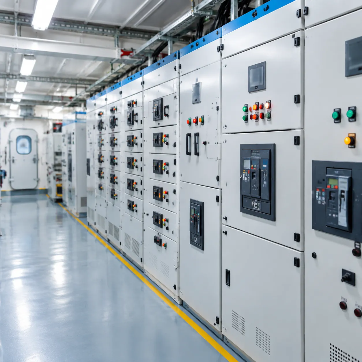
Marine HV Main Switchboards: GIS vs. AIS
The marine high voltage switchboard serves as the central distribution hub. Modern vessels typically implement one of two switchgear designs:
-
- Air-Insulated Switchgear (AIS): Uses atmospheric air as the phase-to-phase insulating medium. AIS provides straightforward visual inspections and accessibility, but it demands larger switchboard room dimensions and strict humidity control to prevent flashovers.
- Gas-Insulated Switchgear (GIS): Uses sulfur hexafluoride (SF_6) gas or eco-friendly alternative gas mixtures sealed inside pressurized metal enclosures. Gas-insulated switchgear on ships reduces footprint by up to 60%, making it ideal for offshore units, container vessels, and cruise liners with limited space.
| Feature | Air-Insulated Switchgear (AIS) | Gas-Insulated Switchgear (GIS) |
|---|---|---|
| Footprint | Larger footprint required | Ultra-compact design |
| Maintenance Access | Direct manual access | Sealed units, specialized tools needed |
| Environmental Sensitivity | Vulnerable to salt mist and moisture | Impervious to ambient humidity and dust |
| Lifecycle Servicing | Periodic contact cleaning and gap checks | Gas pressure monitoring and leak checks |
Vacuum Circuit Breakers (VCB) and SF_6 Units
High-voltage switching creates intense electric arcs that must be quenched instantly. We utilize heavy-duty high voltage marine circuit breaker units designed for severe duty cycles:
-
- Vacuum Circuit Breakers (VCB): The standard choice across most modern ships. Arc interruption takes place inside a hermetically sealed vacuum interrupter bottle. They offer rapid quenching, zero toxic gas emissions, and exceptional mechanical endurance with minimal contact erosion.
- SF_6 Circuit Breakers: Employ sulfur hexafluoride gas to extinguish arcs. These breakers operate reliably in ultra-high fault current applications, though they require routine pressure tracking to ensure dielectric strength remains stable.
Sourcing certified marine electrical parts and equipment ensures circuit breakers and replacement modules meet classification breaking capacities under dynamic sea states.
Marine Propulsion Transformers and Step-Down Units
Shipboard distribution networks rely on specialized transformers to step down voltage levels from generation (3.3 kV to 11 kV) to low-voltage hotel, deck, and auxiliary distribution (440 V / 230 V).
-
- Propulsion Transformers: Often built as multi-pulse units (such as 12-pulse, 24-pulse, or 36-pulse configurations) to cancel out harmonic distortions generated by drive inverters.
- Auxiliary Step-Down Transformers: Typically cast-resin dry-type units (Class F or H insulation) that eliminate oil-leak hazards, withstand mechanical vibration, and provide self-extinguishing fire performance in engine rooms.
Electric Propulsion Motors and Variable Frequency Drives (VFD)
In marine electric propulsion systems, HV power drives high-output propulsion machinery efficiently:
-
- Propulsion Motors: Large synchronous, induction, or permanent magnet motors running in the multi-megawatt range deliver immediate torque to fixed-pitch or azimuth thrusters.
- Variable Frequency Drives (VFDs): Water-cooled Pulse Width Modulation (PWM) or Active Front End (AFE) frequency converters modulate speed and torque, slashing fuel consumption and reducing thermal stress across propulsion lines.
HV Marine Cables, Screening Layers, and Stress Termination Cones
High voltage cables require distinct structural protection to handle extreme dielectric stress:
-
- Conductor and Insulation: Multi-strand copper conductors insulated with high-grade Cross-Linked Polyethylene (XLPE) or Ethylene Propylene Rubber (EPR).
- Screening Layers: Semi-conductive inner and outer layers paired with a metallic copper tape screen ensure uniform radial electrical fields, eliminating localized insulation stress.
- Marine Cable Stress Cones: Critical stress termination cones are fitted at every cable end to control dielectric gradient spikes where the insulation shield is cut back. Sourcing tested marine electrical components and spare parts guarantees that terminations and cold-shrink sleeves maintain watertight integrity and resist partial discharge breakdown over time.
Mandatory Safety Protocols and Isolation Procedures
Working around high voltage installation on board ship electrical equipment leaves zero margin for error. Managing voltages ranging from 3.3 kV to 11 kV requires rigid isolation workflows, mechanical fail-safes, and strict personal protection. We implement standardized routines to eliminate accidental re-energization and mitigate arc flash hazards during installation and maintenance.
Permit to Work (PTW) and Sanction for Test (SFT) Workflows
High voltage safety on ships relies on formal documentation routines to transfer and control electrical operational authority:
-
- Permit to Work (PTW): Issued only after the equipment is isolated, locked out, proven dead, and bonded to earth. It guarantees that the circuit remains grounded and completely de-energized for the entire duration of physical repair or installation work.
- Sanction for Test (SFT): When insulation resistance or breaker timing tests require disconnecting the safety earths, the PTW must be temporarily suspended. The SFT document delegates restricted control to the authorized testing engineer to conduct live-state or pressure diagnostics under monitored conditions.
Both documents are core pillars of our shipboard safety and compliance management procedures, ensuring no simultaneous conflicting tasks occur on the same HV feeder.
Castell Key Mechanical Interlocking Safety Systems
We rely on the Castell key interlock system to prevent human error during switching sequences. This mechanical trapped-key setup guarantees a strictly defined sequence of operations:
-
- The vacuum or SF6 circuit breaker must be racked out and locked open before the interlock releases Key "A".
- Key "A" unlocks the shipboard high voltage earthing switch, allowing the operator to close the earthing blades onto the busbar or cable circuit.
- Closing the earthing switch releases Key "B", which is the only key capable of unlocking the switchboard enclosure doors or terminal access panels.
This mechanical trap prevents anyone from opening an energized HV panel or closing an earthing switch onto a live busbar.
Proving Dead: The Live-Dead-Live Protocol
Never assume a circuit is dead based solely on breaker position or visual indicators. Before touching any high voltage busbar or terminal, we follow the non-negotiable Live-Dead-Live verification method:
-
- Test the Detector: Check the approved, high-voltage non-contact or contact testing probe against a dedicated portable proving unit to confirm the instrument functions properly.
- Test the Circuit: Apply the HV detector to all three phases of the isolated equipment to confirm absolute absence of voltage.
- Re-test the Detector: Immediately verify the detector against the proving unit again. If the tester fails on this second check, the circuit dead-check is invalid and must be repeated with a functional unit.
Fixed Earthing Switches vs. Portable Earthing Leads
Grounding the system discharges residual capacitive energy and protects personnel against back-feeds. Marine switchgear utilizes two primary grounding configurations:
| Earthing Method | Application & Location | Key Safety Features |
|---|---|---|
| Fixed Earthing Switches | Integrated inside the marine high voltage switchboard enclosure on busbars and incoming feeder lines. | Spring-assisted, fault-make rated mechanism capable of closing safely against a live short circuit without catastrophic failure. |
| Portable Earthing Leads | Applied directly to motor terminals, propulsion transformers, or disconnected cable ends. | Heavy-duty copper cluster leads with screw-clamp terminals; applied only after verifying dead with an HV detector. |
Arc Flash Boundaries and Essential Marine PPE Gear
An arc flash inside an enclosed marine switchboard room can generate blast pressures exceeding 2,000 lbs/sq ft and temperatures over 35,000°F (19,400°C). We establish clear safety zones and enforce strict Personal Protective Equipment (PPE) standards during switching, racking, and maintenance:
-
- Arc Flash Protection Boundary: Defined approach distance within which personnel must wear certified arc-rated clothing. Non-essential crew members must remain outside this zone during live operations.
- Arc-Rated Switching Suits: Minimum 40 cal/cm² rated full-body suits, including hood and face shield with chin cups, used when racking breakers or testing.
- Dielectric Safety Equipment: Class 4 (up to 36 kV rated) insulating rubber gloves paired with leather outer protectors, safety boots with electrical hazard (EH) soles, and flame-retardant undergarments.
- Switchboard Room Mats: High-dielectric safety rubber matting installed across the entire operating deck in front of all HV switchboards.
Shipboard High Voltage Installation and Cabling Practices
Proper routing, termination, and grounding are vital when handling high voltage installation on board ship electrical equipment. Marine environments subject cabling to severe vibration, humidity, and thermal cycling, leaving no room for sloppy workmanship.
Cable Tray Segregation, Bending Radius, and Mechanical Protection
HV cables must run on dedicated cable trays separated from low-voltage power, instrumentation, and control lines to prevent electromagnetic interference and physical cross-damage.
-
- Segregation Distance: Maintain a minimum clearance of at least 300 mm from low-voltage cables, or route them in completely separated, enclosed metallic raceways.
- Bending Radius Limits: Never bend marine high-voltage cables tighter than manufacturer limits. For single-core and three-core armored cables, we maintain a minimum bending radius of 12x to 15x the overall cable diameter to prevent micro-fractures in the insulation.
- Mechanical Protection: Route lines clear of cargo handling areas, fuel lines, and high-heat surfaces. Use heavy-gauge stainless steel cable covers where physical impact risks exist.
Bulkhead Transits and A-60 Fire Stops
Every high-voltage penetration through watertight bulkheads and fire divisions must maintain the vessel's structural integrity. During our technical shipbuilding construction supervision services, we verify that every high-voltage cable penetration meets strict class rules:
-
- Modular Transit Frames: Use approved multi-cable transit (MCT) frames with certified elastomeric insert blocks sized precisely to the cable outer diameter.
- A-60 Fire Integrity: Apply certified intumescent sealant and fire-stop materials to prevent flame spread, smoke migration, and toxic gas bypass between compartments.
- Watertight Sealing: Ensure compression wedges are torqued strictly to manufacturer limits to withstand dynamic hydrostatic pressure without crushing internal cable layers.
Marine Cable Stress Cones and Terminations
Improper terminations are the leading cause of insulation breakdown in shipboard high-voltage systems. Stripping the metallic screen disrupts the uniform electrical field, concentrating electrical stress at the cut edge.
-
- Semi-Conductive Layer Stripping: Use dedicated scoring and peeling tools. Never nick or score the underlying cross-linked polyethylene (XLPE) or EPR insulation.
- Stress Termination Cones: Install cold-shrink or heat-shrink stress relief cones over the screen cutback. These cones smooth out high-voltage flux lines and prevent localized dielectric failure.
- Track-Resistant Tubing: Apply anti-tracking heat-shrink sleeves over the insulation to resist surface tracking caused by salt-laden, humid marine air.
Bonding, Grounding, and Shield Earthing Requirements
Managing sheath voltages and circulating currents is critical for equipment reliability and crew safety.
| Component | Standard Installation Practice | Primary Purpose |
|---|---|---|
| Metallic Screen (Shield) | Solidly earthed at switchboard and motor termination ends (or single-point earthed with Class approval). | Discharges capacitive charging currents and maintains zero potential on outer layers. |
| Cable Armor (Braid/Tape) | Bonded directly to the vessel hull via dedicated brass grounding glands. | Provides low-impedance fault return path and mechanical protection. |
| Cable Trays & Supports | Continuous earth bonding across joints, strapped to hull structure every 15–20 meters. | Prevents stray static voltages and static spark hazards. |
| Equipment Enclosures | Direct copper bonding strap to vessel shipboard earth grid. | Protects personnel from dangerous touch voltages during earth faults. |
Testing, Commissioning, and Diagnostic Methods for Shipboard High Voltage Systems
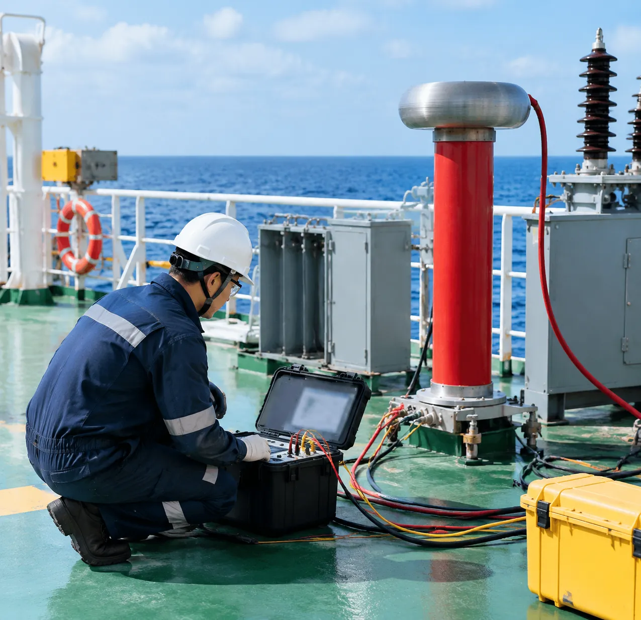
Essential Diagnostic and Verification Methods
| Diagnostic Test | Primary Objective | Typical Standard / Threshold | Target Equipment |
|---|---|---|---|
| Insulation Resistance (IR) & PI | Assesses moisture ingress and bulk dielectric integrity | PI > 2.0 (10-min / 1-min ratio); IR > 100 MΩ | Switchboards, generators, cables |
| VLF / Hi-Pot Pressure Testing | Stresses insulation to reveal latent physical damage | 0.1 Hz AC overvoltage per IEC standards | Marine HV cabling, terminations |
| Partial Discharge (PD) Analysis | Identifies micro-voids, tracking, and localized insulation failure | Online acoustic/TEV sensors; offline PD < target pC levels | Switchgear busbars, transformers |
| Breaker Timing & Dynamic Contact Resistance | Validates pole synchronization and contact wear | Simultaneous pole closing within strict ms limits | Vacuum and SF6 circuit breakers |
Insulation Resistance (IR) and Polarization Index (PI) Testing
We use busbar insulation resistance testing and PI profiling as the baseline check for all HV assets.
-
- Test Voltages: Applied test voltage ranges from 2.5 kV DC to 5 kV DC depending on system ratings (3.3 kV to 11 kV).
- Polarization Index (PI): Measures the ratio of the 10-minute resistance value to the 1-minute value. A ratio below 1.5 flags contamination or moisture absorption, while values above 2.0 confirm healthy insulation.
- Discharge Procedures: We always ground components after DC testing to dissipate residual capacitive charges safely.
High Potential (Hi-Pot) and Very Low Frequency (VLF) Pressure Testing
Overvoltage testing ensures that cable runs, stress cones, and bus assemblies can withstand transient operational surges without flashover.
-
- VLF Advantage: We apply Very Low Frequency (0.1 Hz) AC testing instead of continuous DC Hi-Pot on polymeric cables to prevent trapped space charges that degrade solid dielectric insulation.
- Pass/Fail Criteria: The insulation must withstand the test voltage for the specified duration (typically 15 to 60 minutes) without breakdown or leakage current spikes.
Online and Offline Partial Discharge (PD) Monitoring
Localized electrical discharges across small insulation voids degrade equipment over time. We utilize advanced partial discharge marine switchgear diagnostics to spot faults before catastrophic flashovers occur:
-
- Online Monitoring: Non-intrusive testing utilizing Transient Earth Voltage (TEV) and High-Frequency Current Transformers (HFCT) while switchboards remain under normal load.
- Offline Diagnostics: High-sensitivity bench tests during planned dockings to map the exact location of voids in cable terminations and motor windings.
Circuit Breaker Timing and Dynamic Contact Resistance
A vacuum circuit breaker marine unit must clear high-energy faults in milliseconds to protect the rest of the shipboard grid.
-
- Contact Timing: Measures opening, closing, and auxiliary contact synchronization to prevent phase mismatch during high-current switching.
- Contact Resistance (Ductor Test): Micro-ohm measurements across closed main contacts identify pitting, erosion, and mechanical misalignment that lead to localized thermal runaway.
For complex retrofits and periodic classification surveys, our technical teams deliver turn-key commissioning via our specialised vessel services, ensuring all marine electrical insulation testing adheres strictly to class society standards.
Preventive Maintenance and Troubleshooting Routines
Maintaining a high voltage installation on board ship electrical equipment requires strict, condition-based inspection routines to prevent flashovers, insulation breakdown, and costly off-hire time. We focus on non-intrusive diagnostics and routine physical servicing to ensure continuous operational reliability across demanding fleets, such as those supported by our offshore engineering vessel services.
| Maintenance Task | Key Diagnostic / Inspection Focus | Standard Frequency Interval |
|---|---|---|
| Infrared Thermography | Busbar joints, cable lugs, disconnectors | Every 3 to 6 months (under full load) |
| Space Heater & Seal Check | Enclosure gaskets, thermostat operation | Monthly & during dry dock layup |
| Breaker Integrity Verification | SF₆ gas pressure, vacuum bottle wear | Semi-annually / per manufacturer cycles |
| Insulation & Surface Cleaning | Salt deposits, carbon dust, tracking paths | Annually during scheduled shutdowns |
Thermal Imaging and Infrared Thermography on Switchboard Busbars
Routine infrared (IR) surveys allow us to identify thermal anomalies without taking switchboards offline:
Target Areas: Bolted busbar joints, breaker primary disconnect contacts, cable terminations, and potential transformer (PT) connections.
Inspection Protocol: Conducted while the marine high voltage switchboard operates under a minimum of 40–50% electrical load.
Diagnostics: Detect micro-resistance build-ups and loose connections early, preventing localized overheating before it escalates into phase-to-phase faults.
Maintenance of Anti-Condensation Space Heaters and Enclosure Sealing
Moisture is the primary catalyst for dielectric breakdown at sea. We maintain active humidity defense via:
Thermostatic Space Heaters: Regular verification of heating elements inside switchboards, generators, and motor terminal boxes to ensure automatic engagement when equipment is de-energized.
Enclosure Integrity: Inspecting neoprene door seals, IP-rated enclosure gaskets, and gland plate seals to block salty sea air ingress.
Drain Plugs & Breathers: Clearing desiccant breathers and one-way condensate drains on deck-mounted equipment and auxiliary transformers.
SF6 Gas Pressure Verification and Vacuum Bottle Integrity Checks
High-voltage circuit interrupters demand precise physical verification to guarantee fault-clearing capabilities:
SF6 Gas Density: Monitoring pressure gauges and temperature-compensated density switches on gas-insulated switchgear (GIS) units to prevent dielectric quenching failure.
Vacuum Interrupter Testing: Inspecting vacuum circuit breaker marine units for contact erosion and performing high-potential (Hi-Pot) testing across open contacts to confirm vacuum bottle integrity.
Mechanism Lubrication: Applying synthetic, non-gumming lubricants to trip latches, charging springs, and mechanical interlocks.
Cleaning Procedures, Insulation Contamination Control, and Moisture Prevention
Surface contamination on insulators creates conductive tracking paths under high-voltage stress:
Dry Cleaning Methods: Using lint-free wipes, vacuum cleaners with non-metallic nozzles, and high-purity isopropyl alcohol to clear conductive dust and salt residues from busbar supports and porcelain insulators.
Non-Abrasive Blasting: Employing dry ice (CO2) blasting during major overhauls on heavily contaminated propulsion stator windings to clear carbon build-up without surface abrasion.
Post-Cleaning Testing: Performing busbar insulation resistance testing and polarization index checks immediately following maintenance to confirm zero moisture absorption before re-energizing the installation on vessels running critical LNG carrier tanker services.
Maritime Regulations and STCW Compliance Standards
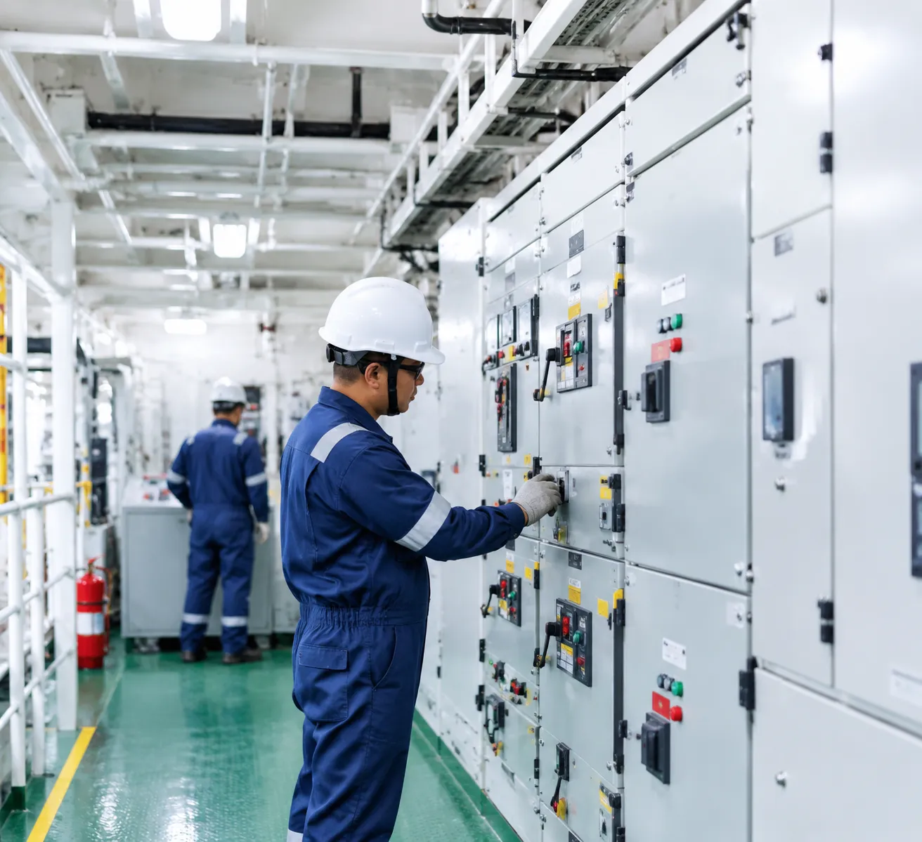
Operating high-voltage power networks offshore leaves zero room for regulatory shortcuts. Every high voltage installation on board ship electrical equipment must adhere strictly to international maritime safety frameworks, statutory flag state rules, and classification society requirements to prevent catastrophic arc flash incidents, system blackouts, and electrical fires.
IEC 60092-503 and SOLAS Chapter II-1 Electrical Standards
We align all shipboard high-voltage designs and modifications with core international statutory codes:
-
- SOLAS Chapter II-1 (Part D): Enforces essential electrical service continuity, emergency power availability, and personnel safety boundaries for equipment operating above 1,000V AC.
- IEC 60092-503: Sets global engineering benchmarks for AC supply systems on ships with voltages from 1 kV up to 15 kV, defining insulation clearances, creepage distances, enclosure IP ratings, and circuit separation rules.
- Safety Interlocks & Segregation: Demands mechanical key interlocking (such as Castell systems) and partition walls to isolate HV switchgear compartments from low-voltage controls.
Our commitment to rigorous safety and statutory alignment is detailed through our established marine quality compliance processes.
Classification Society Rules (DNV, ABS, Lloyd's Register)
Major classification societies impose stringent structural and testing benchmarks before any marine HV installation receives operational approval:
| Classification Body | Primary Focus for Marine HV Systems | Mandatory Compliance Check |
|---|---|---|
| DNV | Redundant power paths, bus-tie arc containment, dynamic load sharing | Type approval of vacuum circuit breakers and routine VLF testing |
| ABS | Marine propulsion transformers, space heater verification, cable routing | Bulkhead transit penetration integrity and insulation monitoring |
| Lloyd's Register (LR) | Earth fault detection methods, switchboard containment, short-circuit ratings | High-potential withstand verification and partial discharge baseline checks |
Integrating these class requirements into day-to-day vessel operations is a vital part of our ship technical management protocols.
STCW Requirements for ETOs and Marine Engineers
Under the STCW (Standards of Training, Certification and Watchkeeping) 2010 Manila Amendments, working on marine high-voltage switchboards requires certified competence:
-
- Electro-Technical Officers (ETO): Must hold operational and management-level HV certification covering isolation procedures, fault-finding, and Sanction for Test (SFT) workflows.
- Marine Engineers (Operational & Management Level): Must demonstrate proficiency in high-voltage safety rules, switching sequences, fixed earthing switch operations, and emergency blackout recovery procedures.
- Safe Working Procedures: Requires mandatory documented Permit to Work (PTW) administration, the use of calibrated high-voltage PPE (minimum Class 4 insulated gloves and arc-rated suits), and strict adherence to proving-dead isolation steps.
Frequently Asked Questions
What voltage threshold is classified as high voltage on ships?
Under international marine classification rules and standards like IEC 60092-503, any AC voltage level exceeding 1,000 V AC (1 kV) between conductors, or 1,500 V DC, is officially classified as marine high voltage. In standard commercial shipboard practice, nominal voltages commonly range from 3.3 kV up to 15 kV.
Why do large cruise and container ships use 6.6 kV or 11 kV instead of 440 V?
Modern vessels require massive electrical capacity to power electric propulsion pods, heavy thrusters, and expansive hotel loads. By raising the operating voltage to 6.6 kV or 11 kV, we significantly lower the operating current required to deliver the same power (P = \sqrt{3} · V · I · \cos\theta).
Key benefits include:
Smaller cable cross-sections: Drastically reduces total copper weight and simplifies routing.
Lower transmission losses: Minimizes thermal dissipation ($I^2R$ losses) across long cable runs.
Compact switchgear: Keeps switchboard dimensions and breaker frame sizes manageable in tight machinery spaces.
What is the difference between a Permit to Work (PTW) and a Sanction for Test (SFT)?
| Feature | Permit to Work (PTW) | Sanction for Test (SFT) |
|---|---|---|
| Primary Objective | Safe non-live maintenance or inspection | Live testing or high-voltage diagnostics |
| Earthing Status | System must remain isolated and solidly earthed | Earthing leads may be temporarily removed under direct control |
| Work Scope | Mechanical/electrical maintenance, cleaning, component replacement | Hi-Pot testing, VLF testing, insulation resistance, and phasing checks |
| Concurrent Use | Suspended before an SFT can be issued on the same circuit | Cannot coexist with an active PTW on the same zone |
What should you do if an HV earth fault alarm triggers at sea?
Because most high voltage installation on board ship electrical equipment uses neutral grounding resistors (NGR), a single earth fault will generally not cause an immediate total blackout. When the alarm sounds, we follow these immediate troubleshooting steps:
-
- Verify the monitor: Check the central insulation monitoring device and switchboard earth-fault indicators to identify the affected bus section.
- Locate the faulty branch: Use selective circuit breaker tripping sequences on non-essential feeders, or monitor sub-distribution sensors to pinpoint the grounded cable or equipment.
- Switch to redundant systems: Transfer critical marine auxiliary loads or auxiliary propulsion systems to a clear bus segment.
- Isolate and inspect: Once identified, isolate the affected component following full safety lock-out procedures, prove dead, apply earths, and perform an insulation resistance testing check to locate the breakdown.
How often should partial discharge and insulation resistance tests be conducted on board?
We recommend following a structured condition-monitoring schedule to catch insulation breakdown before catastrophic flashovers occur:
-
- Insulation Resistance (IR) & Polarization Index (PI): Performed semi-annually, during scheduled machinery overhauls, and verified during newbuilding supervision and sea trial support phases.
- Online Partial Discharge (PD) Monitoring: Run continuously on critical electric propulsion drives, step-down transformers, and main switchboards via permanent acoustic and capacitive sensors.
- Offline Diagnostic Testing: Conducted every 24 to 30 months, or during standard class drydock surveys, to evaluate dielectric degradation on high-voltage cables and stator windings.